This is a modified version of a lab written by Alex Clarke at the University of Regina Department of Computer Science for their course, CS315. Any difficulties with the lab are no doubt due to my modifications, not to Alex's original!
This lab is an introduction to Texture Mapping.
Assignment:
After the lab lecture, you have until next week to:
- Use your own image for texture mapping
- Use repeating and clamped textures
A. Pictorial Overview and Definitions
The following diagram represents the idea of texture mapping:
Some definitions:
- Texture Mapping--"a method of adding realism to a computer-generated
graphic. An image (the texture) is added (mapped) to a simpler shape that
is generated in the scene, like a decal pasted to a flat surface. This reduces
the amount of computing needed to create the shapes and textures in the scene.
For instance, a sphere may be generated and a face texture mapped, to remove
the need for processing the shape of the nose and eyes." (Source: http://www.wordiq.com/definition/Texture_mapping)
- Textures--rectangular arrays of data. The data can be color data, luminance data, or color and alpha data
- Texels--the individual values in a texture array
- Mipmaps--Although we will not be covering this in detail in this
lab. Mipmaps are often discussed with texture mapping. It's something good
to know.
The idea is that you have multiple images to cover multiple levels of detail. For instance, for an object far away, you have a texture or a mipmap that is small and with little detail, and for closer objects, you have a texture that is large and detailed.
Taking an example from msdn (Search for EasyTex). If you are looking at a stop sign from far away, you see only a red circle. As you get closer, you can see it is a red shape with some letters. Finally, you see the entire stop sign. You might specify the mipmaps to look something like this:

If you did not specify different levels of detail, WebGL would try to squish the large stop sign into a smaller image. It would combine the red sign with the white letters, and you would get a pink blob instead of a round, red circle.
B. Coding Overview
For the following discussion you should download Lab6.zipand follow along. Download and expand it. Move it so that the resulting directory, Lab6, is a peer to the Common folder that we've been using throughout the course. (The html files have script statements that reference files in the Common folder.) If you need another copy, here's a zip file containing Common.
In this lab Javascript will have to work with local files - your texture files. Web browsers block Javascript from loading files directly from the local filesystem. Instead, files must be loaded from a web server, via a URL. (This limitation is a security precaution.) You should use either Visual Studio Code with Live Server, or WebStorm to run your programs. Both of these start a local web server thread to handle the local file requests.
If you simply use Chrome or any other modern browser to open, for example, Lab6Exercise.html, you won't see anything. If you check the Javascript console, you'll see an error message.
The Steps in Texture Mapping are the following:
- Create a texture name and bind it to the type of texture we will be creating
- Specify texture properties and the texture image
- Enable texture mapping
- Provide the mapping between texture coordinates and the object's coordinates.
B1. Texture objects and names/handles
OpenGL and OpenGL ES use the glGenTextures() command to assign a name (which is really a number - an index - like a handle) to one or more texture objects. WebGL uses the similar createTexture() command. It creates one texture name/handle as if glGenTextures() was called, and uses it to initialize and return a WebGLTexture object. It doesn't allocate space to hold the texture data/image yet. That happens when we bind it. (This is a pattern in WebGL and is analogous to how we create and bind buffers.) The code to generate a new WebGLTexture object is as follows:
    var texName;
    //allocate a texture name
    texName = gl.createTexture();
Now that we have a texture name/handle, we need to specify some information about the type of texture we are working with. We do this with bindTexture(). There are four types of textures in WebGL: 2D, cube map, 3D and 2D array. In this lab, we will be working with 2D textures, which is indicated by the gl.TEXTURE_2D in the following code:
    //select our current texture
    gl.bindTexture(gl.TEXTURE_2D, texName);
Calling gl.bindTexture() for the first time with a particular name/handle initializes the texture object as a 2D texture with some related default values or properties. Once you bind a texture name as either 2D or cube map, you must always bind it as such or you will get warnings and errors. The other properties of the texture can be modified while it is bound.
We will call gl.bindTexture() again later with this same name/handle. When gl.bindTexture() is called with a previously created texture object, that texture object becomes active. Therefore, the next call to gl.bindTexture() will make texName the current texture.
B2. Texture Properties and the Image
At this point we've got a texture name/handle (via createTexture()) and we've created a texture and bound it to that name/handle with the bindTexture() command. Now we can specify some properties or parameters for the texture. If we don't specify any parameters, the default values will be used.
The following are some parameters that we may want to set. The comments provide some idea as to what each of these calls is doing. For more details about these parameters and their defaults, you should consult the MDN page for texParameter[if] .
    //The texture wraps over the edges (repeats) in the x direction
    gl.texParameteri(gl.TEXTURE_2D, gl.TEXTURE_WRAP_S, gl.REPEAT);

    //The texture wraps over the edges (repeats) in the y direction
    gl.texParameteri(gl.TEXTURE_2D, gl.TEXTURE_WRAP_T, gl.REPEAT);

    //when the texture area is large, repeat texel nearest center
    gl.texParameteri(gl.TEXTURE_2D, gl.TEXTURE_MAG_FILTER, gl.NEAREST);

    //when the texture area is small, repeat texel nearest center
    gl.texParameteri(gl.TEXTURE_2D, gl.TEXTURE_MIN_FILTER, gl.NEAREST);
Next, we can specify the image we are going to use. In this example checkImagw is referencing a 2-dimensional array of RGB values representing a checkerboard pattern. We set the texture to the image pointed to by checkImage with the following code:
gl.texImage2D(gl.TEXTURE_2D, 0, gl.RGBA, checkImageWidth, checkImageHeight,
                             0, gl.RGBA, gl.UNSIGNED_BYTE, checkImage);
See the MDN page for texImage2D for function details.
B3. Switching Textures
While you are drawing, you need to specify which texture you are going to be working with. You can have multiple textures loaded into your Rendering Context. You switch between them by calling gl.bindTexture. Remember, the first time you call gl.bindTexture it creates a texture object with default values for the texture image and texture properties. You can then load a texture and configure it. The second time you call it with the texture name, that texture data becomes the current texture state.
gl.bindTexture(gl.TEXTURE_2D, texName);
B4. Provide the Mapping between Texture Coordinates and the Object's Coordinates.
You have to specify which part of the texture image is going to fit or map onto the object. Texture coordinates are often referred to as s and t. For a texture image, s and t are in the range of 0 to 1. The mapping itself is similar to setting a color for each vertex. To map the checkerboard texture onto a square, we would provide vertex and texture coordinate arrays that would look like this:
var points =
[
  //square
	-2.0, -1.0,  0.0,
	 0.0,  1.0,  0.0,
	-2.0,  1.0,  0.0,

	-2.0, -1.0,  0.0,
	 0.0, -1.0,  0.0,
	 0.0,  1.0,  0.0,
];

var texCoords =
[
  //square
	0.0,  0.0,
	1.0,  1.0,
	0.0,  1.0,

	0.0,  0.0,
	1.0,  0.0,
	1.0,  1.0,
];
Graphically, we should see the mapping as the following:
B5. A Simple Texture Mapping Shader
To add texture mapping capability to your shader program, you need to do the following:- New technique: Connect active textures to the shader. You have to tell the shader what texture image unit(s) your texture(s) is (are) bound to. This information is sent to a special type of uniform in the fragment shader called a sampler.
- Send the texture coordinates to the vertex shader. Do this like sending vertices, colors and normals.
- Pass the texture coordinates to the fragment shader. This is like passing a color or vertex position, except texture coordinates usually have 2D coordinates (vec2).
- New technique: Look up texture values in the shader. In the fragment shader you use the GLSL function texture to look up a value in the texture sampler at the interpolated texture coordinates.
Connect Active Textures to the Shader
To use a texture you must declare a uniform of type sampler* in your fragment shader. Samplers come in 2D and cube flavours. You will be using sampler2D. The sampler is used to help look up values in a texture correctly. Each sampler in your shader program will be connected to a single texture image unit. WebGL 2.0 supports a minimum of 16 simultaneous texture samplers. For starters you will only be using one texture image unit, and that is unit 0, but you can determine your system's limit with this Java code: console.log(gl.getParameter(gl.MAX_COMBINED_TEXTURE_IMAGE_UNITS));.
uniform sampler2D tex;
    //The default texture image unit is unit 0
    gl.uniform1i(gl.getUniformLocation(program, "tex"), 0);
Look Up Texture Values in the Shader
You use the special GLSL function called texture to look up values in a texture. You provide it with a sampler that is connected to a texture image unit that has been configured to look up values in a certain way from a specific texture image. The value to look up is controlled by the texture coordinates. Consider the following example from the Checkers demo:
#version 300 es
precision mediump float;

in vec2 TexCoord;
uniform sampler2D tex;
out vec4 fragColor;

void main()
{
	fragColor = texture(tex, TexCoord);
}
Multi-Texturing
As you write more advanced programs, you may wish to use more than one texture at the same time to achieve certain effects such as adding detail, bump mapping or gloss mapping. To do this you create, bind, set parameters, and load data into multiple texture names, then you bind them to multiple texture image units and send their numbers to the shader like this:
    //Configure two separate texture names, just like for simple texturing
     .
     .
     .
    //Connect the texture units you plan to use to samplers in the shader
    gl.uniform1i(gl.getUniformLocation(program, "tex0"), 0);
    gl.uniform1i(gl.getUniformLocation(program, "tex1"), 1);
    //Bind texture names to texture units
    gl.activeTexture(gl.TEXTURE0); //switch to texture image unit 0
    gl.bindTexture(gl.TEXTURE_2D, textures[0]);   //Bind a texture to this unit
    gl.activeTexture(gl.TEXTURE1); //switch to texture image unit 1
    gl.bindTexture(gl.TEXTURE_2D, textures[1]);   //Bind a different texture to this unit

   //Draw textured item
   ...
Note that gl.activeTexture takes OpenGL constants of the form gl.TEXTUREn whereas you only send the number, n, of the texture unit to the sampler in the shader. WebGL 2.0 specifies a minimum of 16 texture units, so n can be a value from 0 through 15. The number can be higher if your implementation supports it, which is likely — even my laptop with Intel integrated graphics supports 16.
C. Repeating a Texture Pattern or Clamping It
In the example that we are using, we have specified that we would like to repeat the pattern, but we are currently not making use of this repeating feature. When we repeat a texture, it provides a "tile" effect. The following code specifies that we will repeat the texture map.
    gl.texParameteri(gl.TEXTURE_2D, gl.TEXTURE_WRAP_S, gl.REPEAT);
    gl.texParameteri(gl.TEXTURE_2D, gl.TEXTURE_WRAP_T, gl.REPEAT);
But in order to see any results, we have to assign texture coordinates outside the range [0,1]. For instance to get a 3x3 tile of the checkerboard on our square, we would specify the texture coordinates like this:
var texCoords =
[
    //square
	0.0,  0.0,
	0.0,  3.0,
	3.0,  3.0,

	0.0,  0.0,
	3.0,  3.0,
	3.0,  0.0,
	//Leave triangle stuff as is....
];
Try it out!
Question 1: In your lab document, place a screenshot of the demo, modified to the s,t coordinates as above.
Graphically, we should see the mapping as the following (the red lines are placed in the texture map to help show that the texture is repeated three times)
Instead of specifying that we want to repeat the texture, we can specify that we want to clamp or mirror repeat the texture. In this case, we change the gl.REPEAT to gl.CLAMP_TO_EDGE or gl.MIRRORED_REPEAT. Here's an example of clamping:
    gl.texParameteri(gl.TEXTURE_2D, gl.TEXTURE_WRAP_S, gl.CLAMP_TO_EDGE);
   gl.texParameteri(gl.TEXTURE_2D, gl.TEXTURE_WRAP_T, gl.CLAMP_TO_EDGE);
What does this mean? Any values greater than 1.0 are set to 1.0, and any values less than 0.0 are set to 0.0. For instance, if we use gl.CLAMP_TO_EDGE with the above texture coordinates, then a small copy of the texture will appear in the bottom left-hand corner of the object. To the right will be a "clamp" of the texture at s=1. To the top, will be a clamp of t=1.
Graphically, we could see the mapping as something like this (again, the red lines are in the image to point out the original texture in the bottom left-hand corner).
Question 2: In your lab document, place screenshots of the demo, modified to use clamping and wrapping with the s,t coordinates as above.
D. Working with Image Files
The checkerboard pattern in the above example was a simple black and white image that we stored into an array. It is possible to generate other images procedurally in various ways, but you may want to use more complicated pictures — for instance art or photographs.
WebGL allows you to easily load any image supported by your browser, including images created in other canvases, with a modified version of texImage2d. It is documented in the WebGL specification, but has no equivalent in OpenGL ES. Here is how you would typically use it.
First you create an image tag. You can do it programatically with javascript, but it is easier to make a hidden img tag with an ID like this:
<img src="pic.png" id="mypic" hidden />
    // WebGL often loads images upside down. This will correct that.
    gl.pixelStorei(gl.UNPACK_FLIP_Y_WEBGL,1);

    // Get the IMG tag by its ID
    var mypic = document.getElementById("mypic");

    // Load data from the IMG
    gl.texImage2D(gl.TEXTURE_2D,
                  0,                //mip map level
                  gl.RGBA,          //internal texel format (in graphics memory)
                  gl.RGBA,          //external texel format (in system memory)
                  gl.UNSIGNED_BYTE, //external texel data type
                  mypic             //image data source - IMG tag, ImageData object,
                                    //  HTMLCanvasElement or HTMLVideoElement
                                    //  (frame number required)
                  );
Although modern OpenGL supports images of arbitrary sizes, WebGL is like older OpenGL. It only allows images that have both a width and height that are a power of 2. For instance, valid sizes would be: 64 x 16, 512x512, 256 x 256, 128 x 128, and 16 x 4. Some invalid sizes would be: 100 x 100, 6 x 4, 5 x 5, and 2 x 22.
Let's modify our demo code to use a second texture unit that is associated with an image loaded from our web page.
Copy the code in checkers.js from //Make texture unit 0 active down to and including the last of the four gl.texParameteri calls. Paste it below the gl.texImage2D call. In the pasted code change "TEXTURE0" to "TEXTURE1" and "texNames[0]" to "texNames[1]".
,
Now to load the image into the new texture. Below the pasted code add the code in the "In your .js file" box, above.
At this point texture unit 0 holds the checkboard image and texture unit 1 holds the "mypic" image from the web page.
If you run the program now you won't see any change because we haven't yet told the fragement shader to use texture
unit 1. To do that change the last parameter of gl.uniform1i(gl.getUniformLocation(program, "tex"), 0); from "0" to "1". Run the program again and you should see:
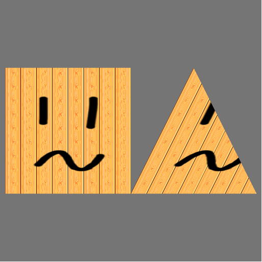
Question 3: In your lab document place a screenshot of your browser window showing the smiley-textured square and triangle, labeling it "Question 3".
E. References
The following are a list of references that were used in the making of this lab:
- MSDN Reference: OpenGL VII: Scratching the Surface of Texture Mapping
- OpenGL Texture Tutorial (from www.nullterminator.net)
- Word IQ--Definition of Mipmap
- WordIQ--Definition of Texture Mapping
- The Red Book (OpenGL Programming Guide 2nd Edition) Chapter 9
- Sample Code from the Red Book
- Nehe
- More Information on BMP Format
- Non power of two extension.
F. Exercise
Answer Question 1 and Question 2, as stated above. Place answers in lab document labeled "Question 1" and "Question 2"
Goals:
- Edit your own picture and make it a texture map (3 different sizes)
- Tile your texture across the image
- Clamp and center your image on the object
This week's lab exercise was originally based on Lesson 6 from NeHe OpenGL tutorials. It has been mostly rewritten, but still uses some textures provided in that tutorial.
Start with Lab6.zip. If you are working locally, use Visual Studio Live-Server or WebStorm to open the html files. There's instructions to do that at the top of this lab. This will allow the Javascript code to access files from your local file system.
Modify the code by following these steps:
- First, run the code to see how it works. You should see a cube with a NEHE logo. You can use the 'a' key to toggle a spinning animation.
- Pick three of your favorite images and use an image editor to crop a portion of an image and save it in the web image format of your choice (jpg, png or gif are probably best). Save the three images with these sizes: 512 x 512, 500 x 500, and 256 x 256. Store these files in the Data directory.
- Edit the code in Lab6Exercise.js so that you can switch
between the three image files that you created by pressing keys. Do NOT reload the texture using
texImage2D
every time you switch - only rebind textures you have already loaded. Use the '1', '2', and '3' keys to switch among the images.
(6 marks - three for keys that switch, three for switching properly) - Run the result. Try all three images. Do they all work on your computer? From the lab notes tell me whether they are guaranteed to work on all OpenGL implementations. Which ones wouldn't? Why? Question 4: Place your answers in the lab document, labeled "Question 4".
- Modify the code so that your image is tiled 3x3 on the surface
of the cube (similar to the image below). Save a copy of this code as Lab6_tiled.js and Lab6_tiled.html to hand in.
(6 marks)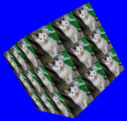
- Modify the code so that your image is in the middle of the
cube with the image "clamped" to edge (similar
to the image below). The "c" key should switch to this mode, and the "t" key should switch back to tiled mode. Save a copy of this code as Lab6_clamped.js and Lab6_clamped.html to hand in. You must use a texture that has multiple colors along its perimeter. Do not use the NeHe texture, as its perimeter is all white.
(6 marks)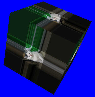
(6 marks--two marks for each file)
(5 marks--for answering question)
(TOTAL /30)
BONUS: Specular Mapping and MultitexturingNotice that the fragment shader receives two colours from the vertex shader - one for diffuse and ambient, and another for specular. Both are added together then multiplied by the texture colour. This hides specular highlights when the texture is dark. If you only multiply the texture against the diffuse and ambient colour, you can see the specular highlight across the surface of the whole cube. It is possible to use a second texture to control specular colour independently of the diffuse colour. This can some interesting effects. Combining this with another texture to control the specular exponent (shininess) is one way to accomplish the technique called gloss mapping.
To do this bonus:- Start with a new copy of this week's lab project naming it Lab6_bonus.js and html.
- Add a second texture sampler to the fragment shader.
- Add an appropriate call to setUpTextures to connect a second texture unit to the new sampler.
- Multiply the specular colour by this new texture sampler - it will be the specular map.
- Multiply the diffuse and ambient colour by the original texture sampler - it will be the diffuse map.
- Add the two products together to create the final fragment colour.
- Load two separate textures to two separate texture names in setUpTextures. One will be your specular texture, and the other will be your diffuse. You will find textures in the project that can be used for this purpose. You should be able to figure out which is which from the file names (look for "S" and "D").
- Just before drawing the box, bind the two textures to the two texture units you intend to use.
Deliverables
- Written answer or screenshot to:
- Questions 1, 2, 3, and 4.
- A zip file containing:
- Version of your program with keys 1,2,3 changing textures, named Lab6Exercise.
- Version of your program with repeated textures, named Lab6_tiled.
- Version of your program with clamped textures, named Lab6_clamped.
- One copy of your Data folder
- If you do the bonus, submit that program as Lab6_bonus.js and .html as well as your modified fragment shader.