This is a modified version of a lab written by Alex Clarke at the University of Regina Department of Computer Science for their course, CS315. Any difficulties with the lab are no doubt due to my modifications, not to Alex's original!
Some of the examples mentioned in the lab notes are available here. Note that this code is very old, and is Windows MFC based.
Download the lab's demos here:
The vectors that you send in to your shaders typically represent colours, vertex coordinates, surface normal, and texture coordinates. Since the components of these vectors have different meanings, GLSL provides special accessors that you can use to refer to the components.
    r, g, b, a    Used for colors. red, green, blue, alpha (blend factor)
    x, y, z, w    Used for spatial coordinates like vectors and points.
    s, t, p, q    Used for texture lookups.
These can be added to the end of a vec* variable to refer to one or more components, or to mix and match them. Consider these GLSL examples:
    vec4 red = vec4(1.0, 0.0, 0.0, 1.0);
    vec2 point2D = vec2(1.0, 0.0);

    //make a yellow color starting with red and matching green to the red component.
    vec4 yellow = red;
    yellow.g = yellow.r;

    //Turn red into blue by rearranging the components.
    vec4 blue = red.gbra;

    //Create a partially transparent color from an opaque one.
    vec4 ghostred = vec4(red.rgb, 0.5);

    //Turn a 2D point into a homogeneous 4D point with z = 0.
    vec4 point4D.xy = point2D;
    point4D.zw = vec2(0.0, 1.0);
Accessing and modifying vectors in this way is called swizzling. Try swizzling the colours and coordinates for the triangle in lab demo 1.
[1] In your lab document, submit a screen shot of your modified Lab Demo 1.
For more information on accessing and manipulating vector components refer to section 5.5 of the GLSL ES 1.0 Spec. You should also check section 5.1 for a full list of operators, and 5.11 for details on how basic math operators work on matrices and vectors - generally they are component-wise. Be aware of the exceptions like matrix-matrix multiplication.
In this lab you will begin using built-in shader language functions to help with lighting calculations. Here are some of the commands you should become familiar with. You can find a complete list of built-in shader commands in section 8 of the GLSL ES 1.0 Spec, and you can read more in-depth discussion of their use in the OpenGL and GLSL API man pages. Links to the man pages for individual functions provided below:
You can use C/C++ style control flow statements like if-else, switch-case, and for loops. The while, and do-while loops are in the OpenGL ES GLSL specification, but are optional, and are not included in WebGL.
All of these control flow statements will be used in the lighting shader to help support multiple lights.
There is also a simple example of an if statement in the lighting shader that allows the use of a simple uniform color for things which should not be lit.
The following sections contain a quick review of GLSL control statements, but you should refer to section 6 of the GLSL ES 1.0 Spec for full details.
Functions require prototypes under the same conditions as C++ functions.
Arrays can be passed to functions, but cannot be returned. Arrays are passed to functions as you would expect from C++, but array sizes must be provided in the square brackets of the formal parameter declaration. The argument array must match the size provided in the formal parameter declaration.
Parameters may be qualified as in(default), out or inout. Reference parameters do not exist as such, nor is there any such thing as a reference or pointer in GLSL. You should treat both out and inout qualified parameters as if they were reference parameters.
Overloading of a function name with different parameter types is allowed. Overloading on return type is not, as with C++.
Here is an example of typical function prototype and definition structure, from the GLSL specification:
// prototype
returnType functionName (qualifier0 type0 arg0, qualifier0 type1 arg1, ..., qualifiern typen argn);

// definition
returnType functionName (qualifier0 type0 arg0, qualifier1 type1 arg1, ..., qualifiern typen argn)
{
    // do some computation
    return returnValue;
}
The main function is the entry point for a shader. It takes no arguments, and must have a void return type.
If-Else selection works as you might expect. The conditional expression must evaluate to a boolean. Nesting is allowed.
You only get for loops. The OpenGL ES GLSL 1.0 specification says that while and do-while loops are allowed, but according to Appendix A.4 they are optional in OpenGL ES 2.0 based implementations, so WebGL does not officially support them.
for loops exist, but have some tight restrictions:
Structures are simple data type collections. They do not support member functions.
A structure is defined like this:
        struct light
        {
            vec4 position;
            vec4 color;
        };
Instances of structures are declared like this:
light light1;
Structures may be const or uniform. They may not be varying or attribute.
You use dot notation to access data members of a structure. If the structure is a uniform, this notation is also the name of that member when you request its location. There is no way to get the location of an entire struct. See the example in L4D2's vertex shader and javascript code.
Structures may be initialized with a structure constructor. Constant structures must be initialized in this way. The arguments to a structure constructor must be of the same type and in the same order as in the structure's definition. For example:
light light2 = light(vec4(1.0, 1.0, 1.0, 0.0), vec4(1.0, 0.0, 1.0, 1.0));
Arrays are similar to C++ arrays, but they must be indexed by a constant valued expression in all but one case - when the array is a uniform. This restriction is not as bad as it sounds, since a for loop index counts as a constant - the tight rules on for loops allow them to be expanded at compile time.
Arrays must also be declared with a constant size.
If an array is a uniform, you get the location of items at its indices individually with the index number as part of the name. There is no way to get a location for an entire array. See the example in L4D2's vertex shader and javascript code.
If the colors of two vertices are different, what is the color between the two vertices? For example, what is the color of the center of the triangle defined by these arrays from lab demo 1?
var points = [
	-1, 0, 0,
	 1, 0, 0,
	 0, 1, 0
];

var colors = [
	 1, 0, 0,
	 0, 1, 0,
	 0, 0, 1
];
The answer is that it depends on the interpolation, or shading, model specified. The choices are smooth and flat.
In WebGL 1.0, which you are learning, there is only smooth shading. In smooth shading, the color values are interpolated between vertices. In the above example the color at the center would be gray.
In WebGL 2.0, which is available as an experimental feature in some versions of Chrome and Firefox, you can do flat shading. If flat shading is specified, one vertex is selected as being representative of all the vertices; thus the entire primitive is displayed using one single color. For all primitives it is the last specified vertex in each polygon or line segment. Flat shading is specified with the keyword flat before the data type on an output from your vertex shader and the corresponding input to your fragment shader.
Remember, WebGL 1.0 does not have the flat keyword and when doing lighting, flat shading is impossible to do consistently, and cannot be done at all without using extra geometry.
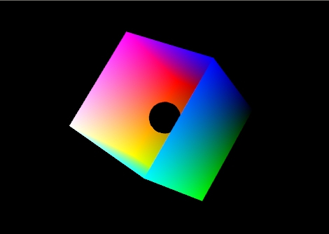
To see the difference between flat and smooth shading, consider the following example. The model is a cube missing its top left side. There is a small black ball inside. Specifically it is the RGB color cube. RGB = (0,0,0) is on the right and RGB = (1,1,1) is on the left.
|
|
| Figure 1: The color cube with smooth shading selected: |
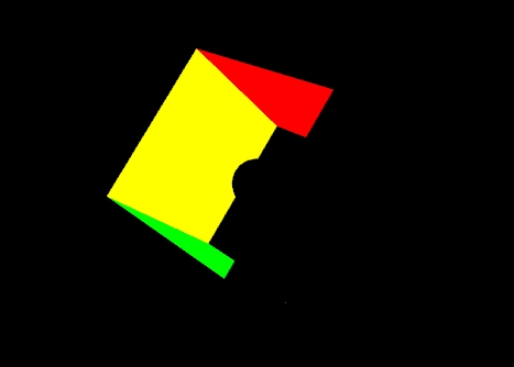
Figure 1 shows the effect of smooth shading. With no lighting effects, it is very hard to distinguish between the faces of the polygons that make up the object. Figure 2 shows the same model with flat shading. The color of each face is entirely the result of the order in which the vertices were specified.
 |
|
Figure 2: The color cube with flat shading selected. |
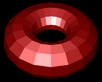
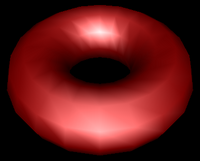
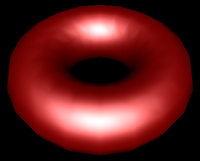
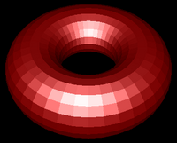
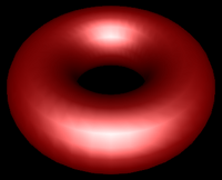
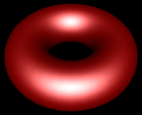
Your vertex shader can output more than just colour and vertex positions. Any vertex attribute can be interpolated as it is sent to your fragment shader. If you choose to send and interpolate only colours you are doing Gouraud shading. You may also wish to interpolate normals and do lighting calculations in the fragment shader rather than the vertex shader. This is called Phong shading. Do not confuse with Phong reflection which you can calculate in a vertex shader. You will learn more about Phong reflection calculations in the next lab.
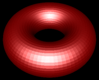
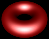
| Flat Shading | Gouraud Shading | Phong Shading |
|---|---|---|
 |
 |
 |
 |
 |
 |
 |
 |
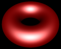 |
| Figure 3:Torus at different resolutions lit with Blinn-Phong reflection and shaded with different shading models. | ||
When you start to work with lighting, you move beyond color to normals, material properties and light properties. Normals describe what direction a surface is facing at a particular point. Material properties describe of what things are made of — or at least what they appear to be made of — by describing how they reflect light. Light properties describe the type and colour of the light interacting with the materials in the scene. Lights and materials can interact in many different ways. Describing these many different ways is one reason shaders are so important to modern 3D graphics APIs.
One common lighting model that relates geometry, materials and lights is the Blinn-Phong reflection model. It breaks lighting up into three simplified reflection components: diffuse, specular and ambient reflection. In this week's lab we will focus on diffuse and ambient reflection.
Diffuse reflection is the more or less uniform scattering of light that you see in matte or non-shiny materials, like paper. The intensity that you see depends solely on the position of the light and the direction the surface is facing. The Blinn-Phong model calculates it using the Lambertian reflectance equation:
Id = md Ld (l · n)
Where:
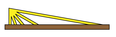
The dot product between l and n corresponds to the cosine of the angle between the two vectors. If they are the same, then the dot product is 1 and the diffuse reflection is brightest. As the angle increases toward 90° the dot product approaches 0, and the diffuse reflection gets dimmer. This change resembles the how a fixed width of light spreads out over a greater area when it hits a surface at different angles, as illustrated in Figure 4.
 |
|---|
| Figure 4: The same width of light covers a larger area as its angle to the surface normal increases. |
Even if the light does not reach a point on the surface directly, it may reach it by reflecting off of other surfaces in the scene. Rather than compute all the complex interreflections, we approximate this with ambient reflection. The ambient reflection is a simple product of the ambient colors of both the light and material. Direction does not factor in. The ambient reflectance equation is then:
Ia = ma La
Where:
A vertex shader that implements all of this is included in Demo 2. Its code is shown below:I = Id + Ia
//diffuse and ambient multi-light shader

//inputs
attribute vec4 vPosition;
attribute vec3 vNormal;

//outputs
varying vec4 color;

//structs
struct _light
{
    vec4 diffuse;
    vec4 ambient;
    vec4 position;
};

struct _material
{
    vec4 diffuse;
    vec4 ambient;
};

//constants
const int n = 1; // number of lights

//uniforms
uniform mat4 p;     // perspective matrix
uniform mat4 mv;    // modelview matrix
uniform bool lighting;  // to enable and disable lighting
uniform vec4 uColor;    // colour to use when lighting is disabled
uniform _light light[n]; // properties for the n lights
uniform _material material; // material properties

//globals
vec4 mvPosition; // unprojected vertex position
vec3 N; // fixed surface normal

//prototypes
vec4 lightCalc(in _light light);

void main()
{
  //Transform the point
  mvPosition = mv*vPosition;  //mvPosition is used often
  gl_Position = p*mvPosition;

  if (lighting == false)
  {
	color = uColor;
  }
  else
  {
    //Make sure the normal is actually unit length,
    //and isolate the important coordinates
    N = normalize((mv*vec4(vNormal,0.0)).xyz);

    //Combine colors from all lights
    color.rgb = vec3(0,0,0);
    for (int i = 0; i < n; i++)
    {
        color += lightCalc(light[i]);
    }
    color.a = 1.0; //Override alpha from light calculations
  }
}

vec4 lightCalc(in _light light)
{
  //Set up light direction for positional lights
  vec3 L;

  //If the light position is a vector, use that as the direction
  if (light.position.w == 0.0)
    L = normalize(light.position.xyz);
  //Otherwise, the direction is a vector from the current vertex to the light
  else
    L = normalize(light.position.xyz - mvPosition.xyz);

  //Calculate diffuse coefficient
  float Kd = max(dot(L,N), 0.0);

  //Calculate colour for this light
  vec4 color = Kd * material.diffuse * light.diffuse
               + material.ambient * light.ambient;

  return color;
}
[2] Debug the second demo. Once you have the demo running, in your lab document, place a screen shot of the second demo.
In this week's second lab demo, a for loop in the init function acquires the uniform locations for all the lights and collects them in an array called light. If you change the number of lights – n – in the shader, be sure to make a corresponding change to the loop in init. Here is the loop:
    // Get and set light uniforms
    light = [];   // array of light property locations (defined globally)
    var n = 1;    // number of lights - adjust to match shader
    for (var i = 0; i < n; i++)
    {
        light[i] = {};   // initialize this light object
        light[i].diffuse = gl.getUniformLocation(program,"light["+i+"].diffuse");
        light[i].ambient = gl.getUniformLocation(program,"light["+i+"].ambient");
        light[i].position = gl.getUniformLocation(program,"light["+i+"].position");

        //initialize light 0 to default of white light coming from viewer
        if (i == 0)
        {
            gl.uniform4fv(light[i].diffuse, white);
            gl.uniform4fv(light[i].ambient, vec4(0.2, 0.2, 0.2, 1.0));
            gl.uniform4fv(light[i].position,vec4(0.0, 0.0,10.0, 0.0));
        }
        else //disable all other lights
        {
            gl.uniform4fv(light[i].diffuse, black);
            gl.uniform4fv(light[i].ambient, black);
            gl.uniform4fv(light[i].position,black);
        }
    }
Classic OpenGL has five material properties affect a material's illumination. They are introduced in the Blinn-Phong model section and implemented in the shaders in lab demo 2. They are explained below.
In this week's second demo, L4D2, the only diffuse and ambient material properties have been implemented. They have been declared for you globally, given default values and sent to the shader. They are called material.diffuse and material.ambient. These correspond to properties the uniform structure called material in the vertex shader.
In that demo let's specify a light blue material. This code should go into your render function just before drawing an object:
    var diffuseColor = vec4(0.5, 0.7, 1.0, 1);
    var ambientColor = scale(0.5,diffuseColor);
    gl.uniform4fv(material.diffuse, flatten(diffuseColor));
    gl.uniform4fv(material.ambient, flatten(ambientColor));
The steps are as follows:
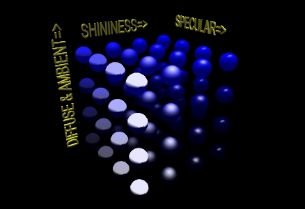
Seeing the effects of varying material properties may help you select the ones you want. In the LIGHTING 1 example pictured below, the program created a 4X4X4 matrix of blue spheres and varied the ambient and diffuse properties along the y-axis, the specular along the x-axis, and the shininess along the z-axis. The values used were as follows:
// set up arrays of various properties
// placed here for convenience
GLfloat materialSpecular[4][4] = {
	{ 0.1f,  0.1f,  0.1f, 1.0f },
	{ 0.33f, 0.33f, 0.33f, 1.0f },
	{ 0.67f, 0.67f, 0.67f, 1.0f },
	{ 0.9f,  0.9f,  0.9f,  1.0f },
};

GLfloat materialAmbDiff[4][4] ={
	{ 0.0f, 0.0f, 0.12f, 1.0f },
	{ 0.0f, 0.0f, 0.25f, 1.0f },
	{ 0.0f, 0.0f, 0.50f, 1.0f },
	{ 0.0f, 0.0f, 1.00f, 1.0f },
};

GLfloat materialShininess[4][1] = {
	{ 0.0f },
	{ 5.0f },
	{ 25.0f },
	{ 125.0f }
};
These values were chosen because they give a relatively even increase in each property as the values change. Figure 7 presents the changes that these properties bring when combined. The color of the spheres are defined by the ambient and diffuse values, and you can see from both the array and the illustration that the colors start off as a very dark blue rise to a bright pure blue. The shininess effect can be observed as the highlight goes from being spread across the entire illuminated hemisphere to a point of light on the surface. If you rotate the matrix about the y-axis, you will see that the highlight disappears when the angles of the reflection no longer hits the viewpoint.
|
| Figure 7: A matrix of spheres showing the range of material properties |
To enable lighting in Core Profile OpenGL you need to write an appropriate shader. With this shader you can enable and disable lighting by writing 1 and 0 respectively to the lighting uniform.
Each individual light source should have color properties, and a position or direction. It may also have other useful properties. The shader for this lab only has one possible light source, but you can extend the idea by creating properties for additional lights.
The lights in this week's lab have two colour properties: Diffuse colour and Ambient colour. The variables for these in the javascript code are LightDiffuse, LightAmbient and LightSpecular.
The diffuse component of the light contributes the most to the general reflectance off an object and is what you can consider the "colour" of the light. Shining a light with red diffuse RGBA settings on a white sphere would give a red coloring to all parts of the sphere that the light illuminates.
The ambient component of the light represents the colour the light has after it has bounced around the environment — the environmental colour. It is an approximation the light's contribution to global illumination. It also allows us to see the shape of an object on the dark side.
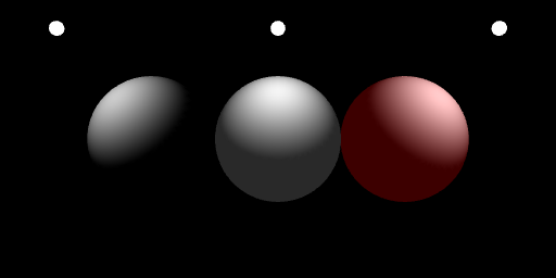
And here is the code used to set up the light colours used on the right sphere in the above example:
    gl.uniform4f(light[0].diffuse, 1, 1, 1, 1);
    gl.uniform4f(light[0].ambient, .3, 0, 0, 1);
The variable light[i].position is used to store the position of the light in this week's lab. The variable light[i].position is bound to a uniform of the same name in the shader.
If you want the light to be positioned relative to the viewer, simply send that position directly to the shader. If you want to position it somewhere in the world, construct a modelview matrix for it and multiply against the light's position as you send it to the shader (Dr. Angel's MVnew.js library actually requires that you do this with the transpose of the matrix). You could use the current state of the modelview matrix to transform the position of the light in the shader, but then the light would be positioned relative to each individual object rather than appearing to be at one place for the whole frame.
The meaning of light[i].position depends on its fourth or w component. If it is 0.0, the light is treated as a directional source. In this case the light is considered to be infinitely far away in the direction indicated by the light[i].position vector. If the fourth component is not 0.0, it is a positional source. Diffuse and specular lighting calculations are based on the location specified by the x, y and z components of the light in eye coordinates. The default position is (0,0,1,0); thus, the default light source is directional, parallel to, and in the direction of the -z axis.
The following call, if issued before any drawing commands, is equivalent to the default light used in this week's lab - in the direction of the viewer, but infinitely far away:
gl.uniform4f(light[0].position, 0.0, 0.0, 1.0, 0.0);
And this call sets the light at the same position as the viewer:
gl.uniform4f(light[0].position, 0.0, 0.0, 1.0, 1.0);
And, finally, this call sets the light two units above the world origin:
    //place this immediately after mv is set by the lookAt function...
    gl.uniform4fv(light[0].position, mult(transpose(mv), vec4(0.0, 2.0, 0.0, 1.0)));
Lighting equations require normals. These are vectors that indicate what direction a surface is facing. For some figures it is easy to calculate the normal. For example the normal for any point on a sphere can be calculated by subtracting the point's coordinates from the sphere's center point. A cube's normals are simply the unit vectors along the major axes - this is what was done in L4D2. Other figures have more complicated normals.
If you have two vectors in the plane perpendicular to a surface you can calculate the normal by taking the cross product of those two vectors. For flat sided figures, you can use any two adjacent edges on a face and use their cross product as the normal for all vertices on the face. For smooth figures, you could take the average of the cross products of all neighboring edges that connect to the vertex. If you know the equation that was used to generate the vertices, you could use derivatives of the equation to calculate the normal.
The following function will take a set of vertices meant for use as TRIANGLES and calculate flat normals for each triangle. You should try it on the cube from the lab notes.
//----------------------------------------------------------------------------
// makeFlatNormals(triangles, start, num, normals)
// Caculates Flat Normals for Triangles
// Input parameters:
//  - triangles: an array of 4 component points that represent TRIANGLES
//  - start: the index of the first TRIANGLES vertex
//  - num: the number of vertices, as if you were drawing the TRIANGLES
// Output parameters:
//  - normals: an array of vec3's that will represent normals to be used with
//             triangles
// Preconditions:
//  - the data in triangles should specify triangles in counterclockwise
//    order to indicate their fronts
//  - num must be divisible by 3
//  - triangles and normals must have the types indicated above
// Postconditions:
//  - the normals array will contain unit length vectors from start,
//    to (start + num)
//----------------------------------------------------------------------------
function makeFlatNormals(triangles, start, num, normals)
{
    if (num % 3 != 0)
    {
        console.log("Warning: number of vertices is not a multiple of 3");
        return;
    }
    for (var i = start; i < start + num; i+= 3)
    {
      var p0 = vec3(triangles[i][0],triangles[i][1],triangles[i][2]);
      var p1 = vec3(triangles[i+1][0],triangles[i+1][1],triangles[i+1][2]);
      var p2 = vec3(triangles[i+2][0],triangles[i+2][1],triangles[i+2][2]);
      var v1 = normalize(vec3(subtract(p0, p1)));
      var v2 = normalize(vec3(subtract(p0, p2)));

      var n = normalize(cross(v1,v2));
      normals[i+0] = vec3(n);
      normals[i+1] = vec3(n);
      normals[i+2] = vec3(n);
    }
}
You should always be sure that the normal is of unit length. This is part of the definition. You should normalize the normal after calculating it. You may also need to rescale or normalize the normal after applying modeling or viewing transformations.
Some transformations will cause the angle between the normal and surface to change. Non-uniform scaling is an example of one such transformation. You will need to correct for this. In the case of non-uniform scaling you need to apply the inverse scale to the normal. To this end, you may want to calculate a separate normal matrix to go along with the modelview matrix.
This exercise is broken into two parts:
Goals:
Instructions
  var octahedronVertices = [
    vec4(-1, 0, 0,1), //0
    vec4( 1, 0, 0,1), //1
    vec4( 0,-1, 0,1), //2
    vec4( 0, 1, 0,1), //3
    vec4( 0, 0,-1,1), //4
    vec4( 0, 0, 1,1), //5
  ];
/10
Your final submission should have one invisible sphere - it should be completely black. Place comments near your changes to the code. Make sure your have written answers to 2, 5 and 7.
/10