Lab 3:
3D Transformations
[For Winter2024 modify as indicated in rubric] This is a modified version of a lab written by Alex Clarke at the University of Regina Department of Computer Science for their course, CS315. Any difficulties with the lab are no doubt due to my modifications, not to Alex's original!
Highlights of this lab:
This lab is an
introduction to Matrix Transformation
Assignment
After the lab lecture, you have one week to modify the files in Lab3.zip:
- Practice modeling and viewing transformations with boxes.html and boxes.js then answer some questions
- Create controllable fingers for a robot arm based on robot_arm.html and robot_arm.js.
Lecture Notes
A. The Classic OpenGL Transformation Pipeline
The classic OpenGL pipeline had two main stages of vertex transformation, each with its own transformation matrix. These were built into the graphics hardware. These days, other transformation pipelines have become possible since transformations are done in the vertex shader. However, in this lab, as in the textbook, we will try to implement the classic pipeline.
Each vertex in the scene passes
through two main stages of transformations:
- Model view transformation (translation, rotation, and
scaling of objects, 3D viewing transformation)
- Projection (perspective or orthographic)
There is one global matrix
internally for each of the two stage above:
Given a 3D vertex of a polygon, P =
[x, y, z, 1]T, in homogeneous coordinates, applying the model view
transformation matrix to it will yield a vertex in eye relative coordinates:
P’ = [x’, y’, z’, 1]T =
Mmodelview*P.
By applying projection to P’, a 2D
coordinate in homogeneous form is produced:
P” = [x”, y”, 1]T =
Mprojection*P’.
The final coordinate [x”, y”] is in a normalized coordinate form and can be easily mapped to a location on the screen to be drawn.
Setting Up The Modelview and Projection Matrices in your shader
Since OpenGL Core Profile always uses shaders, neither the
modelview nor the projection matrix is available. You have to set them
up yourself. The matrices will be allocated and given their values in
the main program, and they will be applied to vertices in the shader
program.
To help us create and manipulate matrices in our main program we
will use the matrix classes and helper functions in MV.js. Each matrix will be initialized to identity if you use the
default constructor. So to create our initial modelview and projection
matrices we would declare two mat4 objects like so:
var mv = new mat4();   // create a modelview matrix and set it to the identity matrix.
var p = new mat4();    // create a projection matrix and set it to the identity matrix.
These two matrices can be modified either by assigning or post-multiplying
transformation matrices on to them like this:
p  = perspective(45.0f, aspect, 0.1f, 10.0f); // Set the projection matrix to
                                              // a perspective transformation

mv = mult( mv, rotateY(45) ); // Rotate the modelview matrix by 45 degrees around the Y axis.
As in this example, we will usually
set the projection matrix p by assignment, and accumulate transformations in the modelview matrix mv by post-multiplying.
You will use uniforms to send your transformations to the vertex shader
and apply them to incoming vertices. Last lab you did this for colors by
making vector type uniforms and for point sizes by making a float uniform. Uniforms can also be matrices.
Here's part of a vertex shader:
//other declarations
//...

//Uniform declarations
uniform mat4 mv; //declare modelview matrix in shader
uniform mat4 p;  //declare projection matrix in shader

void main()
{
  //other shader code
  //...

  //apply transformations to incoming points (vPosition)
  gl_Position = p * mv * vPosition;

  //other shader code
  //...
}
To set the value of uniform shader variables you must first request their location in your JS code, like this:
//Global matrix variables
GLint projLoc;
GLint mvLoc;


//In your init code
// Get location of projection matrix in shader
projLoc = gl.getUniformLocation(program, "p");

// Get location of modelview matrix in shader
mvLoc = gl.getUniformLocation(program, "mv");
Then, (still in your JS) you use a uniform* (GLES
2.0 man page) (WebGL Spec)
function with the uniform location and a local variable to set their value. Do
this whenever you need to update a matrix - usually when the window is resized
or right before you draw something. To set the value of our 4x4 float type
matrices we will use the form uniformMatrix4fv:
//in display routing, after applying transformations to mv
//and before drawing a new object:
gl.uniformMatrix4fv(mvLoc, gl.FALSE, mv); // copy mv to uniform value in shader

//after calculating a new projection matrix
//or as needed to achieve special effects
gl.uniformMatrix4fv(projLoc, gl.FALSE, p); // copy p to uniform value in shader
B. Elementary Transformations
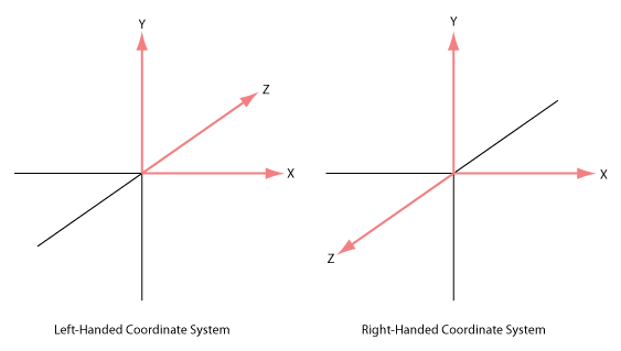
- Right-handed and left-handed coordinate
system: With your right hand line your index finger pointing along the x-axis and your middle finger pointing along thee y-axis. Your thumb will now be pointing along the positive z-axis. Compare to the figure
below. The other system shown is a left-handed coordinate system. It is
sometimes used in graphics texts. A consequence of using the right-handed
system is that the negative z-axis goes into the screen instead of the
positive as you might expect.
- Right-handed coordinate
system is used most often. In OpenGL, both the local coordinate system for
object models (such as cube, sphere), and the camera coordinate system are
use a right-handed system.
- In the following discussion, we assume that all transformation
function calls return a matrix that you will post-multiply onto
Mmodelview, unless the other is specifically
mentioned.
- All transformation functions in this discussion that do not begin
with gl. are equivalent or similar to a classic OpenGL
transformation function and are defined in MV.js. They
all use the float data type for simple values.
Translation:
translate(dx, dy, dz);
Where [dx, dy, dz] is the translation vector.
The effect of calling this function is to create the translation
matrix defined by the parameters [dx, dy, dz] which you should concatenate to the global model view matrix:
Mmodelview = Mmodelview * T(dx, dy, dz);
Where T(dx, dy, dz) =
In general, a new transformation matrix is always concatenated to
the global matrix from the right. This is often called
post-multiplication.
Rotation:
rotate*(angle)
Where angle is the angle of counterclockwise rotation in
degrees, and * is one of X, Y or Z.
rotate(angle, x, y, z);
Classic OpenGL only defined a single rotation function capable of rotating
about an arbitrary vector. A similar function is in MV.js. However,
typically we rotate about only one of the major axes, via the functions rotateX, rotateY, and rotateZ, each of which takes a single argument--the angle of rotation in degrees. These simple rotations
are then concatenated to produce the arbitrary rotation desired.
The effect of calling a rotation matrix is similar to
translation. For example, this:
mv = mult( mv, rotateX(a) );
will have the following effect:
Mmodelview = Mmodelview *
Rx(a);
Where
Rx(a) denotes the rotation matrix about the x-axis for degree
a: Rx(a) = 
Rotation matrices for the y-axis or z-axis can be achieved respectively
by these functions calls:
mv = mult( mv, rotateY(a) ); // rotation about the y-axis
mv = mult( mv, rotateZ(a) ); // rotation about the z-axis
Scaling
scalem(sx, sy, sz);
where sx, sy and sz are the scaling factors along
each axis with respect to the local coordinate system of the
model. The scaling transformation allows a transformation matrix to change
the dimensions of an object by shrinking or stretching along the major
axes centered on the origin.
Example:
to make the wire cube in this week's sample code three times as high, we can stretch it along the y-axis
by a factor of 3 by using the following commands.
     //---SET INITIAL VIEW, END---
     // make the y dimension 3 times larger
     mv = mult( mv, scalem(1, 3, 1));

     //Send mv to the shader
     gl.uniformMatrix4fv(mvLoc, gl.TRUE, mv);

     // draw the cube and axes
     gl.drawArrays(gl.LINE_STRIP, wireCubeStart, wireCubeVertices);
Question 0: Try manipulating the scale of the cube and insert a screenshot showing your results into your lab document.
- It should be noted that the scaling is always about the origin
along each dimension with the respective scaling factors. This means
that if the object being scaled does not overlap the origin, it will
move farther away if it is scaled up, and closer if it is scaled
down.
- The effect of concatenating the resulting matrix to the global model
view matrix is similar to translation and rotation.
- (Somewhat confusingly, the textbook uses two different functions named scale, one with two arguments (a scalar and a vector), and one with a single argument (a vector). The former returns a copy of its second argument (the vector), but with each of its elements multipied by the scalar. The latter returns a 4x4 or 3x3 scaling matrix, with the vector's elements specifying the scaling factor along each axis. You may have to examine your copy of MV.js to make sure you are using the correct function.
C. The Order of Transformations
- When you post-multiply transformations as we are doing and as is
done in classic OpenGL, the order in which the transformations are
applied is the opposite of the order in which they appear in the
program. In other words, the last transformation specified is the
first one applied. This property is illustrated by the following
examples.
- The initial default position for the camera is at the
origin, and the lens is looking into the negative z direction.
- Most object models, such as cubes or spheres, are also defined at
the origin with a unit size by default.
- The purpose of model view transformation is to allow a user to
re-orient and re-size these objects and place them at any desired
location, and to simplify positioning them relative to one another.
Example:
Suppose we want to rotate a cube 30 degrees and place it 5 units
away from the camera for drawing. You might write the program
intuitively as below:
    //---SET INITIAL VIEW, END---
    mv = mat4();  //(This obliterates the previous value of mv--for purpose of this exercise)

    // first rotate about the x axis by 30 degrees
    mv = mult(mv, rotateX(30));

    // then translate back 5
    mv = mult( mv, translate(0, 0, -5));

    // Send mv to vertex shader
    gl.uniformMatrix4fv(mvLoc, gl.FALSE, flatten(mv));

    // Draw the cube...
    gl.drawArrays(gl.LINE_STRIP, wireCubeStart, wireCubeVertices);
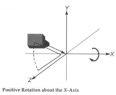
The following figure shows the effect of these transforms:
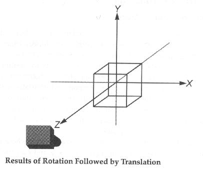
If you run this program, you might be surprised to find that
nothing appears in the picture! Think about WHY.
If we modify the program slightly as below:
    //---SET INITIAL VIEW, END---
    mv = mat4();  //(This obliterates the previous value of mv--for purpose of this exercise)

    // first translate back 5
    mv = mult( mv, translate(0, 0, -5) );

    // then rotate about the x axis by 30 degrees
    mv = mult( mv, rotateX(30) );

    // Copy mv to the shader
    gl.uniformMatrix4fv(mvLoc, gl.FALSE, flatten(mv));

    // Draw the cube...
    gl.drawArrays(gl.LINE_STRIP, wireCubeStart, wireCubeVertices);
The following figure shows the new result:
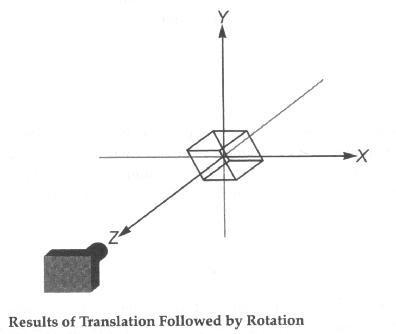
Question 1. In your lab report, describe why the images differ.
D. Modeling Transformation vs.
Viewing Transformation
- OpenGL uses concepts of a modeling transformation and a viewing
transformation.
- The modeling transformation is the product of the
calculations for creating and laying out your model (making sure everything is
correctly positioned and oriented relative to everything else in the model).
The transformation functions scalem(), rotate*() and
translate() can be used to alter the modeling matrix.
- The viewing transformation is the sequence of
calculations for viewing the model (positioning the viewpoint so
that you view the model from the orientation and position you
desire). You can think of this as positioning and orientating the camera. You could also use the combination of scalem(),
rotate*() and translate() for viewing
transformations. The following discussion explains how this
approach works. However, it involves the concepts of local and
global coordinates and could be very confusing to some
students. I would like to suggest students to skip this part
first (notice I labeled it OPTIONAL), and proceed with the
easy approach, lookAt(), discussed next.
OPTIONAL
- First let's look at the following code:
    mv = mult( mv, translate(0, 0, -5) );
    mv = mult( mv, rotateY(30) );
    gl.uniformMatrix4fv(mvLoc, gl.FALSE, flatten(mv));
    draw...(gl...., ..., ...); //Draw the model
Working down to the model's local coordinate system, we
first move the local origin down the negative z-axis by 5
units and then rotate that coordinate system about the y-axis by 30
degrees.
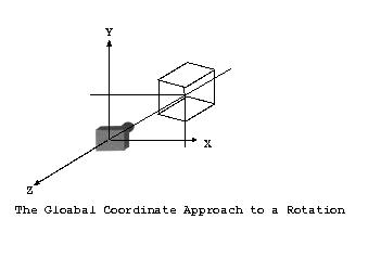
Working up to the global coordinate system from the model,
we first rotate the coordinate system about its origin by -30 degrees,
then move it's origin down the positive z-axis by 5 units. The model
is fixed, but the global coordinate system is rotated and
translated. The viewpoint locates at the origin of the global
coordinate system. Remember that in the global coordinate approach,
the order is reversed, and the orientation order is also reversed.
The following picture illustrates the local approach to a rotation:
The following picture illustrates the global approach to a rotation:
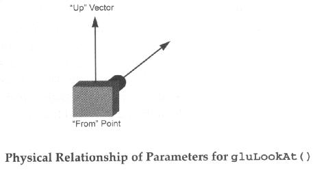
The lookAt() Function:
define a viewing transformation
mat4 lookAt (vec3 eye, vec3 at, vec3 up)
Parameters
  eye: specifies the position of the eye point
  at:  specifies the position of the reference point
  up:  specifies the direction of the up vector
The lookAt() function makes it easy to move both the
"from" and the "to" points in a linear manner. For
example, if you need to pan along the wall of a building located away
from the origin and aligned along no axes in particular, you could
simply take the "to" point to be one corner of the building
and calculate the "from" as a constant distance from the
"to" point. To pan along the building, just vary the
"to" point.
E. Saving and Restoring the Matrix
- Whichever method you use, you will almost always need to either reset the matrix to the identity matrix, or save and restore a previous matrix state. To reset to the identity matrix use code like this:
mv = mat4(); //restore mv to the identity matrix
To save and restore a matrix you can use a matrix stack. Classic OpenGL had
one built in, but, like the rest of the matrix functions, it is missing in
modern OpenGL varieties and must be provided by an external library. You can
use any stack-like data structure that can handle your math library's matrix
class. Javascript's arrays, which provide .push() and
.pop() functions, are perfect.
To make a matrix stack in Javascript, write code like this:
Add to your global variables
//global modelview matrix stack
var matStack = [];
In display, use .push() and .pop() around transforms that should only affect one or a limited set of objects.
matStack.push(mv);

//Apply transforms to modelview matrix
//Draw objects
//... etc ...

//restore old modelview matrix
mv = matStack.pop();
You can store any mat4 matrix on the matrix stack so long as you
remember to pop back to the correct matrices in the correct sequence.
F. Viewport and Projection Transformations
- Once you have learned Modelview transformations, the next step is
to understand projection modes and viewport mapping. I think of this as selecting which "lens" the virtual camera uses--wide angle, long angle, etc. The analogy isn't perfect, since in GL we are not limited to the physical constraints of real lenses.
Viewport Transformation
The viewport is the portion of your window that displays your WebGL content. The gl.viewport() function takes four parameters, which
are used to specify the lower-left corner coordinates and the width
and height of the viewport, or the drawable area in your OpenGL
view. It is best to call it only once you know how big the window
is. That means it should be in your reshape function.
Projection Transformation
There are two basic methods of converting 3D images into 2D ones.
- The first is orthographic, or parallel projection. You use
this style of projection to maintain the scale of objects and their angles
without regard to their apparent distance. MV.js provides
ortho() to do this type of projection.
- The second is Perspective projection. This is the most popular
choice in 3D graphics. A perspective projection matrix can be created with the
perspective() function.
Projection is handled by the MProjection matrix. You do not usually concatenate to the projection matrix as you do with the modelview matrix.
ortho()
  void ortho( GLfloat left,   GLfloat right,
              GLfloat bottom, GLfloat top,
              GLfloat near,   GLfloat far )

  Parameters:
     left, right:
         Specify the coordinates for the left and right vertical
         clipping planes;
     bottom, top:
         Specify the coordinates for the bottom and top horizontal
         clipping planes;
     near, far:
         Specify the distances to the near and far depth
         clipping planes.  Both distances must be positive.
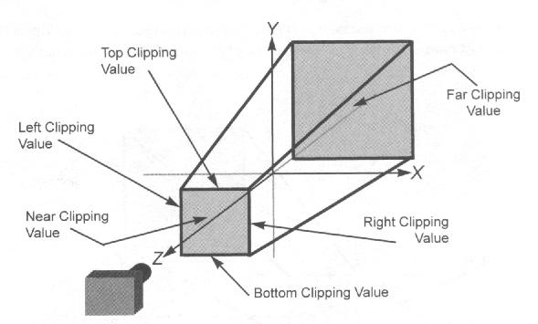
ortho() describes an orthographic projection matrix. (left,
bottom, -near) and (right, top, -near) specify the points on the near clipping
plane that are mapped to the lower left and upper right corners of the window,
respectively, assuming that the eye is located at (0, 0, 0). -far specifies the
location of the far clipping plane. Both near and far must be positive.
The following figure approximates an orthographic (actually it is for frustum() - see below) volume and the ortho()
parameters
perspective()
In old OpenGL systems, a function with the same parameters as ortho() could create perspective transformations. It was called frustum() and though it was powerful, it was not very
intuitive. There is a much simpler perspective command, called
perspective(). Like frustum() it generates a
perspective viewing volume but only a simple one. It lacks the
flexibility of frustum which can be manipulated to achieve
special effects.
  void perspective( GLfloat fovy, GLfloat aspect,
                    GLfloat zNear, GLfloat zFar )

  Parameters:
      fovy:

          Specifies the field of view angle, in degrees, in the y
          direction;

      aspect:

          Specifies the aspect ratio that determines the field of view in
          the x direction.  The aspect ratio is the ratio of x (width) to
          y (height);

      zNear:

          Specifies the distance from the viewer to the near clipping
          plane (always positive);

      zFar:

          Specifies the distance from the viewer to the far clipping
          plane (always positive).
perspective() specifies a viewing frustum into the world
coordinate system. In general, the aspect ratio in perspective
should match the aspect ratio of the associated viewport. For example,
aspect=2.0 means the viewer's angle of view is twice as wide in x as
it is in y. If the viewport is twice as wide as it is tall, it
displays the image without distortion.
The following shows perspective
viewing volume and the perspective() parameters
Assignment
Goals of this assignment:
Master the use of the standard matrix transformations:
- Viewing Transformations: through lookAt or equivalent modeling transformations
- Projection Transformations: through perspective and ortho
- Modeling Transformations: rotate*, translate, scalem, and a matrix stack.
Part 1
Start with boxes.html and boxes.js from Lab3.zip.
As written, this program draws a basic coordinate system with a green x-axis, a red y-axis, and a blue z-axis,. These will be referred to in the instructions as the axes. It also draws a wireframe cube.
With the initial camera settings you are looking directly down the z-axis so you will not see it.
Make the following changes. Add your written answers in your lab report to the questions in the steps below.
-
Comment out the lookAt() call and replace it with a translate() with parameters ( 0, 0, -10 )
Question 2: Is there any change in the display? Why? Why not?
-
Comment out both the lookAt() and translate() lines. Question 3: What happens? Why?
-
Restore the lookAt() call.
-
Take a look at the perspective() call. The original aspect ratio is 1.0.
- Question 4a: What happens when the aspect ratio is 1.0 and you change the canvas dimensions to width="512" height="256" ?
- Question 4b: How about width="256" height="512" ?
- Modify the aspect ratio in the perspective call so that it is an appropriate ratio of width to height based on the actual dimensions of the viewing area. Test the result with the two suggested canvas shapes to be sure you got it right.
Question 5: Provide screen shots of the two resulting images.
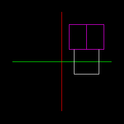
- Move the cube so that it is centered at (1, 0, 0) relative to the axes.
- Draw a second cube after the first - in a new color, if you can - and rotate it 45 degrees around the y-axis.
- Place this rotated cube directly above the first cube. It will be centered at (1, 1, 0) relative to the axes. Be careful of the order of transformations.
-
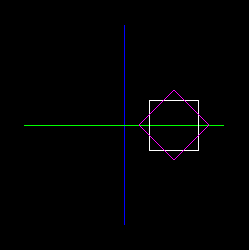
The perspective view makes the two cubes look a little awkward. Try
using orthographic projection instead of the perspective
call. The function for that is: ortho. Use top, bottom, left, right, near and far values that include the whole scene and not much more. See the picture for expected
results (some deviation is OK):
Question 6: Please leave a commented perspective call in your program. Include "Question6" in the comment. Place in your lab report a labelled screenshot similar to the one above.
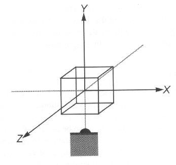
-
Rotate everything (using modeling transformations NOT lookAt) so that you
are looking down at the top of the boxes
and seeing the blue z-axis (and no red y-axis). See the picture for expected results:
If you wanted to leave your x and y axes unchanged, but still see the top of
the boxes, like this:
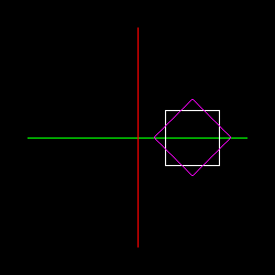
Question 7: Describe how you would
change your code to get the above image.
-
Rotate everything so that you can see all three axes along with the
two cubes. See the picture for expected results:
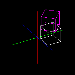
You may use different angles, so long as you can see all three axes and the two wireframe cubes. Question 8: provide a screenshot in your lab report.
/20 marks
Part 2
Start with robot_arm.html and robot_arm.js from Lab3.zip.
- First load the application and see how it works. Try pressing lower and
uppercase 'e' to move the elbow. Try pressing lower and uppercase 's' to
move the shoulder
- Now, add three fingers and a thumb to the robot.
Use matStack.push() and matStack.pop() to separate the transformations for each digit. Do not attempt to "untransform" with an inverse rotate, translate or scale.
- Add some code that will make the finger and thumb move apart
when 'f' is pressed and and together when 'F' is pressed. The center of rotation should be at the wrist.
Your completed robot hand might look something like the following.
 .
.
- Finally, add r/R to rotate the
arm on the X axis so you can see it from above, and t/T button to switch
between solid and wire cubes (examine the cubeLookups and colors arrays to see how you might provide solid cubes).
/20 marks
Deliverables
- Part 1
- A working version of the program showing a result similar to that shown in step 10. Be sure to leave commented code where requested. Please provide your WebGL_Labs folder structure with at least your Lab3 and Common folders inside.
- Document with written answers for the questions in the steps above.
- Part 2
- A working version of the robot arm program with opening and closing claw and at least three fingers and one thumb. Please provide your WebGL_Labs folder structure with at least your Lab3 and Common folders inside.
On-Line References
- Robot Arm Exercise: Neider, Jackie (1997) OpenGL Redbook, Chapter 3, USA: A-W Developers Press.
- Selected pictures: Fosner, Ron (1997) OpenGL Programming for Windows 95 and Windows NT, USA: Addison-Wesley books.